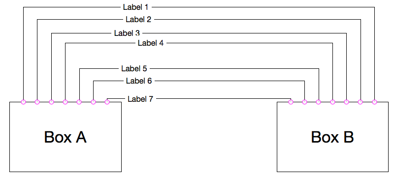
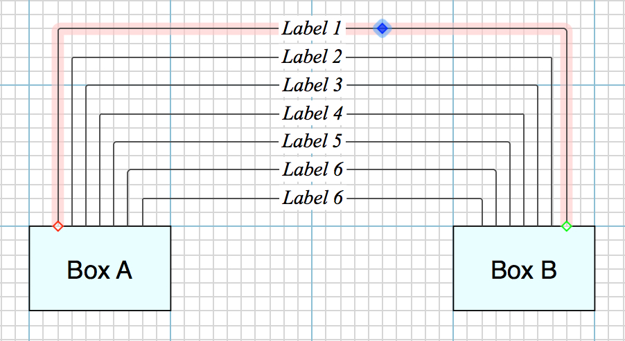
Hi all, I’m trying to make something similar to what the picture shows better-looking, and thanks a lot for the script I found and it’s creator, I was able to divide the boxes evenly with Magnets.
However, after many searches, I still could not find the ways to:
Automatically make the horizontal parts of the lines evenly spaced
Automatically make the line labels aligned vertically
Would be very grateful if someone could provide some tips.
The first step in solving a problem is to identify the problem, accurately. Most people never get past the first step. I will try to take you past it.
If you spend hours on this sort of problem, it is because you do not understand the basic principles of drawing. It has nothing to do with the drawing tool, it is not something you can expect the drawing tool to do for you.
I do not have the time to provide a tutorial, but I can give instructions. Execute the following, in the sequence given. Do not try to form conclusions about it until after you have drawn a few diagrams, that have some complexity, and that you are satisfied with.
Use the Ruler
Use the ruler every single time. Do nothing in a diagram without reference to the ruler. That is the Grid, upon which every object must lie. This is the first of a few key items that cause the difference between a diagram that looks professional or amateur. If you think this step is a waste of time, it means that you do not care enough about drawing to learn the fundamentals, and thus you cannot draw.
Set Canvas/Major & Minor Grid Spacing. I use 2cm major and 10 minor.
Set the colour for Major & Minor to your fancy. I use a dull medium blue for major and light grey for minor.
Set SnapToGrid
You can ShowGridLines or hide it. I show it most of the time, and hide it when the diagram is close to final.
Save this in a template, so that you do not repeat it for each diagram.
Size all Objects to the Grid
That is easy with OG. This eliminates a host of problems, not the least of which is getting things to line up.
Advanced point: if you use object size that is a multiple of 2 Minors, for all your objects (that you intend to line up) your objects will (a) line up perfectly when a bunch of them that are arranged vertically or horizontally, and aligned on their centres. Even the OG Magnets with match up (I seldom set custom Magnets).
Now you have the very basics of drawing. Now you can use a drawing tool affectively. Have fun.
Now for the requests.
You can’t get OG to do that automatically. If OG did that, it would have the same problems as lines that “jump around” when one or the other object is moved (refer to the numerous complaints).
But it is very simple to do, takes a fraction of a second once you get used to it (max one second until you do).
This applies for lines that are far apart, but close to the same horizontal (or vertical) (eg, at opposite sides of the page), that should be on the same horizontal (or vertical). Failure to line up such lines is amateurish.
For each line, double-click on the line, in order to create a MidPoint.
That will create a little blue diamond, which behaves exactly the same way that a handle on an object does. Pick it up and move it.
If you want the diagram to be understood readily, always use orthogonal lines. If you must use diagonals, make them faint, and dotted or dashed, never harsh. (I don’t think I have a diagonal in my entire portfolio.)
It is not worth fiddling with the default Line Handle, use a MidPoint.
If you experience problems with Lines “jumping around”, you need to fix up your magnets. Again, the choice of Magnet Settings in OG, rather than custom, is much easier to use. Get to know them
I don’t think I have ever drawn lines that are close together, that are not evenly spaced.
But it is very simple to do. A couple of fractions of a second.
Use the Grid
In the first instance, assuming you want to maintain the Label as a Label, that is, you have stuck it on the line, it is centred, and it moves with the line. You have the Grid, and it is visible. Moving the Labels such that they line up vertically is a simple task. But I do realise it is fiddly, and not perfect.
Use a Guide
Grab that Ruler (vertical Ruler for vertical Guide, etc) and move it to the position you want, then line up the Labels. This helps visually only, it remains fiddly.
Advanced Method A
To use this option, you must be willing to release the automatic behaviour of Labels on Lines (identified in [1] ).
This is the only option if you use objects that are non-simple (all my objects are somewhat complex) as a Label, because OG allows only simple objects as labels.
To be clear, think of this as a placed object, rather than as a Label.
Use a Guide [2] to mark your desired line-up position.
In the given example (OP) it would be a vertical Guide, a little to the left of the centre between Box A and Box B.
Place each Label (or object intended as a Label) on the canvas, one Grid increment above or below the desired Line, and not on the Line itself.
The object will be Selected. Move it into position simply by ↓ or ↑. Which will move it one Minor Grid increment.
Fiddling eliminated.
Advanced Method B
You need to understand Advanced Method B [3] and be able to use it without labour before you can use this.
Treat all the Labels (or objects) that you intend to line up on the Lines, together. That is, as a group (but do not Group them)
Place them on the canvas, in approximate positions, because you are about to treat them all together
Select them all
Use the Canvas/Alignment function, and Align them. In the example case, it would be Align/CentreLeft and EdgesOnGrid.
If you had not placed them exactly an integral number of Minors apart vertically, you can do that now. Use the same tool to Space them evenly, and type in your Minor value
the Labels (or objects) should be perfect aligned, left edges as well and vertically spaced
Grab them (they are already a Selected collection) and move them onto the Lines
• Two clicks, a couple of keystrokes if required, and one drag
Once you have a handle on this method, you can execute it away from the lines, in an empty part of the canvas, and move them as a bloc. That permits fine spacing away from the interference of the Lines. This is demanded when objects are used, and the content of each object (as distinct from merely the edges) needs to be lined up against the others.
Depending on the broader context of your content, consider making the labels a table of labels, rather than labeling the lines themselves. Do either step 1A or step 1B, then step 2.
1A) To make a bunch of new labels:
Create 1 text label (not on a line).
From the Arrange menu, choose ‘Make Table’.
Drag the waffle handle down to add more rows.
1B) To turn a bunch of existing text labels into a table:
Arrange your free-floating labels vaguely in the arrangement you want. (The labels in your screenshot are close enough, if they weren’t on their lines.)
Select them all.
From the Arrange menu, choose ‘Make Table’.
To connect your shapes to the table labels:
Drag a line from each magnet on Box A to the relevant label in your table.
Drag a line from each magnet on Box B to the relevant label in your table.
Depending on the kinds of edits you tend to make to your diagrams, you may find the table more or less manageable than regular line labels. For example, you can quickly change the labels to be left vs center aligned, or change the text of one label and they’ll sort themselves out. On the other hand, if you switch from a horizontal stack to vertical, you now have to un-group your table and repeat the steps in 1B).
I really couldn’t thank you enough for your detailed explanation and generous sharing.
Initially, after multiple Labels on the Lines were selected, I freaked out and struggled for re-enabling those grayed-out Alignment Inspector buttons.
Later I decided to post my confusions and call for help here because I realized I under Geometry Inspector, the slider represents the reposition of the label along the line was shown as something similar to a rough percentage, instead of a fixed absolute value. This was very different then what I thought.
Fortunately the real job was done afterwards with Grid and Guide. And yes dragging and fine-tuning the positions one by one was a bit fiddly just like GraffleGuru indicated.
It’s such a great thing to be inspired by you guys, the tricks I had learned will definitely be beneficial for me to improve my efficiency.
I have the same question (about the line, not the labels), but the grid is not always the answer. I frequently have a detailed diagram that I need to edit, and that could entail adding 4 more lines to an existing set of 16 lines, but cramming them into the same horizontal space, and spacing them evenly.
Aligning to a grid introduces an “integer” problem, and what I really have is a floating point problem.
Ideally I’d like to have midpoints behave like objects, e.g. be able to select N midpoints and click “Distribute horizontally” the same way I can with a rectangle.
In fact I’ve even toyed with the idea of putting a little invisible rectangle in the middle of all of my connectors, with an internal line, just to make redistributing them easier. But that seems like a horrible Rube-Goldberg-esque solution to what ought to be a fairly simple feature to implement in code, and what would be tremendously useful to a lot of people.
The Grid is always the answer. If I have not conveyed that in my explanation, then I have failed. Let me labour on it a bit more.
The Grid, in and of itself, is not an answer, to any particular problem.
The Grid, is always the backbone, the structure, upon which the correct answer to any problem can be found. The Grid is the standard, the rule[r], that any answer must conform to, in order for the answer, and all the other answers on the canvas, to be valid and problem-free.
The corollary is important:
Without the Grid, the answer to anything will be sub-standard and problematic.
The answer on the canvas that does not conform to the standard will stand out as invalid, problematic.
The answer itself, well, that depends on the object: Lines; Shapes; Labels; anything, will have additional requirements based on the type of object, but the first requirement is for it to conform to the standard that you have set for the canvas.
The Problem
Exactly. I wouldn’t state it like that, but I know what you mean, you are right.
Alignment with the Grid is a first principle of a good diagram, and it carries a compliance burden for all the objects on the canvas. If a Shape that does not conform is added, that introduces a problem, which can be described as:
the conforming Shapes are integer, whereas the non-conforming Shape is non-integer.
Now if you understand the Grid, see if you can understand this: integer divisions of a Grid unit are quite acceptable. Why ? Because they have the Grid in mind.
That is easy. But it takes a bit of labour to explain it it text form.
Ugly as sin.
Exactly, the “science” of the lunatic.
Since you are not deranged (addicted to the back door), engage with the direct method, and manipulate it until it works for you.
Yes. I will give complete answers for [A] and [B] separately. Each answer will hopefully increase your understanding of the other answer.
The Answer • A • Orthogonal Line, Even Spacing of
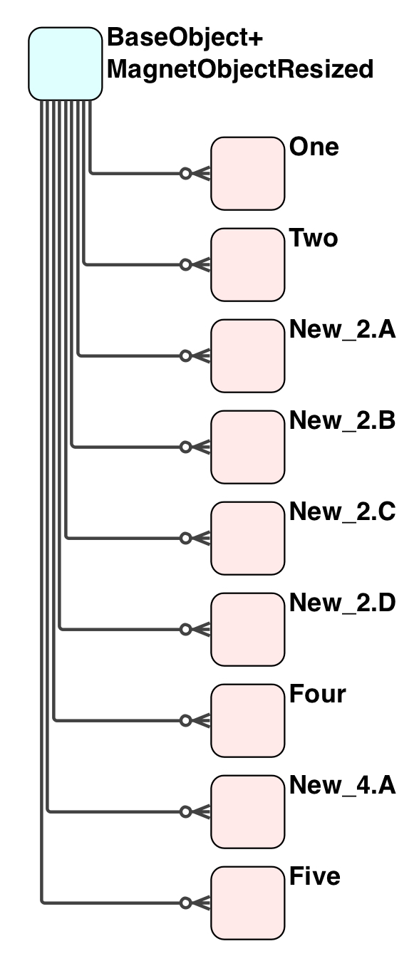
Let’s grab an example. These are all standard objects, with perfected Magnets; text positioning; etc, from a single generic object placed on the Stencil.
AlignToGrid and EdgesOnGrid set, so the placement of each object was simple and correct (conforming)
The Magnet are: three, centred on the left side; seven, centred on the bottom. (If I add four connectors, that will blow the limit.)
The Magnets are placed on precise integer-divisions of a Grid unit: one-half-Grid-unit in this example.
The Lines are dead easy: orthogonal, no MidPoints required. That was the design criteria when perfecting the Magnets. Yes, the Magnets, because all objects must conform to the one standard, which is The Grid
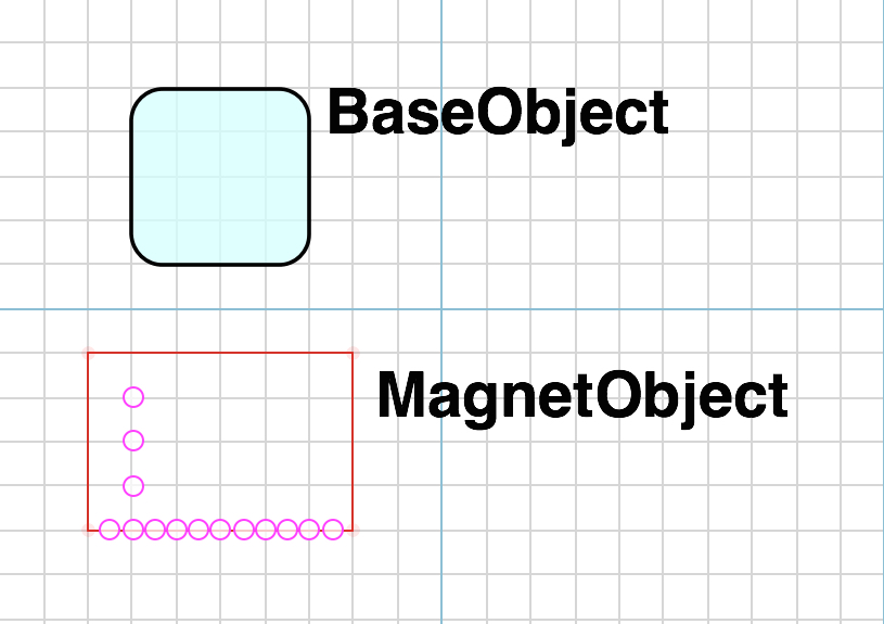
Now for the MagnetObject. It is a variant of that which I have described in several posts as the single most useful object, that I have on every Stencil, the InvisbleObject that answers all demands: the least of which is to overcome annoying OmniGraffle bugs and inconsistent behaviour; the more of which is to provide at element for scenarioos such as this.
Start with a Rectangle that is the size of the BaseObject, and expand it one Grid unit to the left and right.
Fill White with 0% Opacity.
Give it a thin red Stroke, so that it is visible. The last thing you will do to it is remove the Stroke, to make it invisible. That allows you to locate it; pick it up; and move it precisely, without drama.
Arrange the Magnets precisely on Grid-unit-integer-divisions. In this example I have eleven Magnets on the bottom, centred, spaced one-half-Grid-units apart.
You can mess with its hair if you like, as long as you do not forget the governing principle and the effect of rebelling against it.
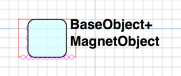
Here is an example of someone who does not “like” the lines spreading past the edges of the BaseObject. Simply select and resize the MagnetObject to the size of the BaseObject.
Fixed one likey likey problem and created a new problem: the Lines are inside the boundary, but he has lost the perfect even spacing between the Lines, that matches everything on the canvas.
The first thing required is to deal with your InvisibleRectangle.
Now that is a great idea, it is along the same lines as my InvisibleObject (although mine probably has more uses due to experience). As you gain experience, you will find more uses for it; more cases where it is a solution. So whatever I say next does not subtract from that good idea.
But this has to do with Lines, not Objects. So an Object-oriented (hate the term) solution is not appropriate for a Line problem.
You are excited about it, so you need to get that, an Object-oriented solution to a Line problem, out of your head. And engage wit the Orthogonal Line and its manipulation capabilities.
The same goes for your idea of [scripted or not] distribution of Magnets on object edges: exaplained in [Answer A], we need the Magnets on GridPoints, regardless of the object size.
The Grid
Using the Grid and Grid-oriented object as detailed above and in other posts, in a couple of hundred intense diagrams, orthogonal Lines are no problem at all, they work perfectly. That includes perfect alignment of the lines on the Grid, or half-Grid-units. This is for OG 5, it may well be broken in OG 6 & 7.
Since I have a carefully chosen Grid, and the sizing of all objects conform to the Grid, and the Magnets of all [connected] Objects conform to the Grid or half-Grid-units, orthogonal lines are dead easy.
SnapToGrid is essential for a decent drawing of any kind, and of course, if you are using a Grid properly, it is doubly essential (it would be a staggering, self-invalidating contradiction to use-the-Grid and not-use-the-Grid at the same time)
If you have set SnapToGrid set, the orthogonal Lines SnapToGrid, just like Objects (again, you don’t need an object to make that happen)
In most cases MidPoints are not required, the Lines are already on the Grid or half-Grid-units, meaning consistency across the entire canvas.
eg. for all the examples in this post, above this sentence, MidPoints are not required. There is no handle (blue rectangle) for a line that consists of just two segments.
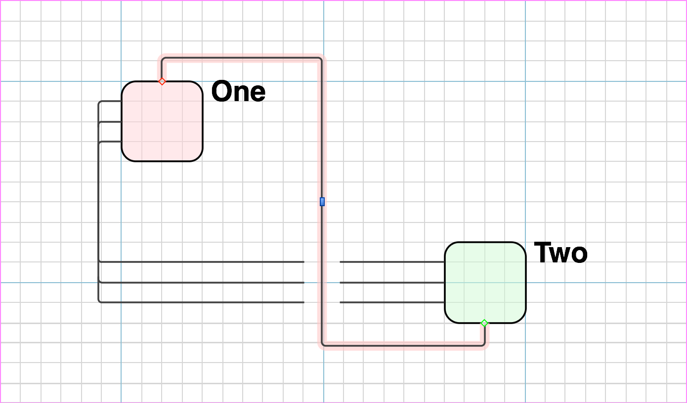
B.1 • Orthogonal Line, No MidPoint
In this example, I have drawn a new orthogonal Line that is three segments, it does have a default handle. The Line is already on a GridLine, and the handle is of course on the GridLine. I did not do anything other than connecting the line to the two relevant Magnets.
Now if I pick up that Handle and move it, it (the Handle) will SnapToGrid
No MidPoint necessary. No extra Shape necessary.
Get used to handling orthogonal Lines in it default state, before deciding that you need a MidPoint.
Exception. Due to bugs related to other settings that you may have; proximity to other Lines and Objects, the placement of Lines may not work as easily as shown, and then yes, you need a MidPoint.
B.2 • MidPoint
One cannot work with something unless what knows what it is. What exactly is a MidPoint ?
Recall, an Object or a GroupedObject is located in a specific Layer, and it can be moved around fairly independently
Whereas a Line is also located in a specific Layer, and it can be moved around fairly independently, a MidPoint is a point (co-ordinate) on the canvas. This may or may not be a limiting factor, it depends on your usage.
Again, this is why, if you set things up correctly, the orthogonal Lines will not require MidPoints, and you don’t have to get into this level of object manipulation.
You can move the line around, as a whole, or you can select one or more MidPoints and move them around.
If you have SnapToGrid set, the MidPoints too, will be on GridLines. If you need half-Grid-units, just crank the Grid down temporarily, for the duration of manipulating that Line.
Exception. Due to bugs related to other settings and proximate objects, a MidPoint may not be on a GridLine. Simply grab the errant MidPoint using the cursor (not the arrow keys) and move it left and right, or up and down, and it will get back onto a GridLine.
Of course you can select a MidPoint or a few, and use the arrow keys: that will move the MidPoint one Grid-unit at a time.
Use the minimum number of MidPoints necessary for each particular Line, and get habituated in that. It makes a difference in the automatic segments that will be created and where they are placed, as well as when you need to move a bunch of Lines together.
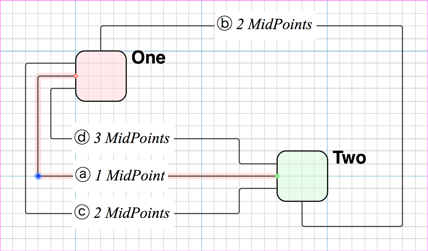
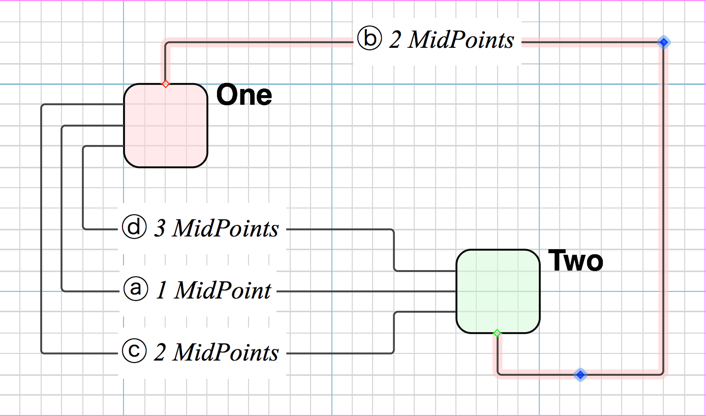
B.3 • Orthogonal Line with MidPoint
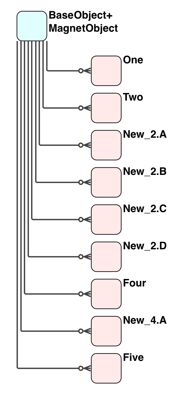
Let’s use a simple example that hopefully covers the issues that exist in a complex, real-world requirement. Here we need four lines between the Objects, and enough space for labels without crowding. First we just connect the lines. (One can draw a Line, a segment at a time, by clicking one MidPoint [where one wants it] at a time, but that is non-simple.) Of course, they are crowded; in the wrong place. Just one line has three segments, and therefore a Handle.
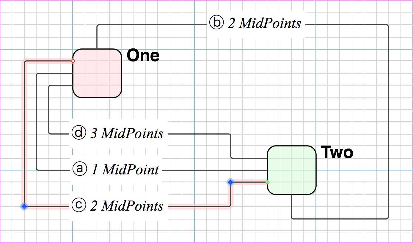
Let’s arrange the Lines; add labels; arrange again for label spacing, and then explain it. Notice how every single MidPoint is located on a GridPoint; the Objects are squared off on GridPoints; and the Magnets are on GridPoints. Life is easy when everyone follows the same set of rules.
One MidPoint
ⓐ The simplest Line-with-a-MidPoint, just one. Three segments as automatically created, but one MidPoint. Compare against the [Initial (No MidPoints) ]
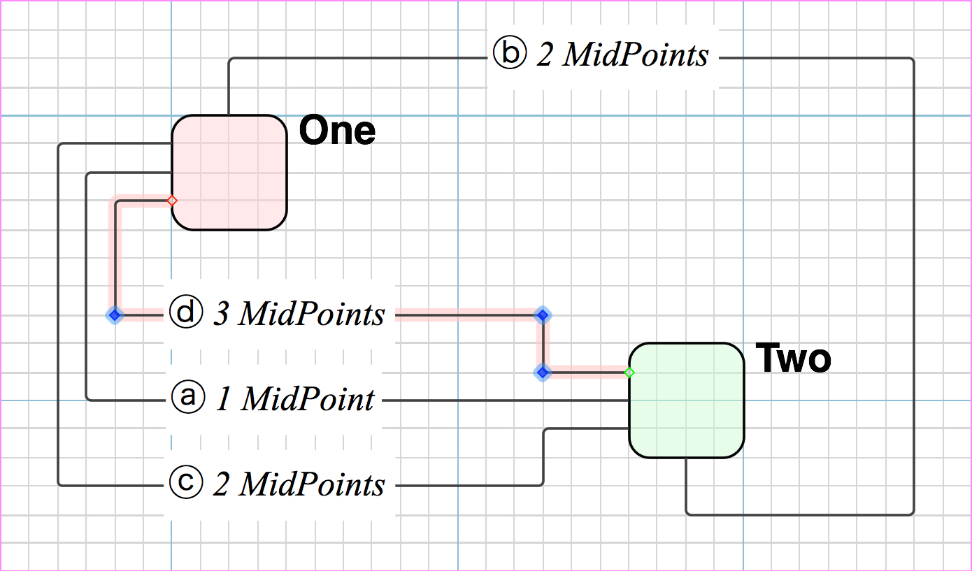
ⓑ Here is an example where we want the Line in a completely different location to that which was automatically created. The first MidPoint (top right) is enough to place the line outside the crowded space, and to eliminate crossed lines (an important principle). The second is to give the line consistent even spacing away from the object.
ⓓ A rare case. The Line required just two MidPoints, but the automatic placement of one particular line segment did not fall on a GridPoint. The creation of the third MidPoint fixed that.
Hmmm. I wonder if my task could be accomplished by scripting OG.
Conceptually it’s very simple. The big question is whether midpoints are selectable as discrete objects. I have an ancient version of OG, which supports AppleScript instead of .js, but I can still choose Copy as AppleScript.
On a line without an added midpoint I get:
make new line at end of graphics with properties {point list: {{232.9804, 512.4524}, {582.42, 545.6638}}, line type: orthogonal, stroke color: {0.000000, 0.000000, 1.000000}, head type: “FilledArrow”, head scale: 0.5}
If I move one of the “little,” automatically-generated midpoints that all elbow connectors have, and then copy again, I get the same properties. So that datum doesn’t get saved.
With an added midpoint I get:
make new line at end of graphics with properties {point list: {{232.9804, 512.4524}, {244.6641, 531.125}, {582.42, 545.6638}}, line type: orthogonal, stroke color: {0.000000, 0.000000, 1.000000}, head type: “FilledArrow”, head scale: 0.5}
(emphasis mine)
and this new point is saved, so if that could be detected then these “extra” points could be distributed horizontally or vertically.
Thanks for the great information GraffleGuru. This is very helpful and will save a lot of frustration. Are the magnets supposed to snap to grid? – I can magnify and hand place them reasonably well but they just don’t seem to want to snap to grid like objects and lines do, and if they do it seems inconsistent.
Your logic is correct, Midpoints are a saved item as a property of a Line. That proves that a MidPoint is not a discrete object.
Scriopting is definitely a possibility, but sorry, I can’t help you with it. Try @draft8, he comes up with some great scripts.
I used to perform a full Extract-Translate-Generate SQL from my data models. But when OmniGroup moved from OG 4 to OG 5, with the then new development team, they changed the internal database to a decrepit RecordFilingSystem that was massively obese and full of duplication (JSON or XML like), the filesize quadrupled. I gave up.
Although purchased, OG 6 and 7 are not useable for me. I remain with OG 5, and I am slowly moving my diagrams to another drawing tool that does not remove features with each “upgrade”.
You are welcome. I was hoping to give directions for people who are serious grafflers, in order to save time and frustration.
First …
The list of lost features and capabilities is long, and I have not compiled a terse list. In an attempt to serve the moderator’s public request “What Lost Features do you want Returned”, I started posting detailed requests for return of each feature, but they censored my posts, so I stopped writing for the darkroom. I got as fas as posting about six items from a list of 12 important items, the rest (not so important) are about 20 in number.
Regarding precise placement of Magnets; etc, in many ways OG 4 behaved better but it had a bad bug on Retina displays, so I had to move to OG 5 and live with a new set of problems that OG 4 did not have: the duplication; the quadrupled file size; the non-intuitive “Intuitive” interface, and the consequences thereof. It drives me mad. But it is still much more precise in this regard than OG 6 and 7. If you have not used OG 4 and 5, you have nothing to compare with, and so you might be quite happy with OG 6 and 7.
So, with OG5, yes, absolutely, by intention, all my Magnets are placed on GridPoints or integer-divisions of grid units (as described in the previous post). The Magnets are not supposed to SnapToGrid (I did ask for exactly that a decade ago), but they are easy enough to place on GridPoints.
Whereas that is one of the behaviours that has gone haywire in OG 6 and 7, placement is difficult because it jumps around like a squirrel on a hotplate.
Also, in OG 5, once you get a few Magnets started on an object, in the intended locations (say 3 of the 11 Magnets in the MagnetObject in my previous post), the subsequent Magnets can be placed easily, they snap to a location relative to an existing Magnet.
Magnets do Snap to specific positions on the edges of an Object: the 0.25; 0.5; 0.75 marks. Use Command-drag with the Magnet tool to relieve it from that default behaviour. Then you can drag slowly and precisely. You can also drag to (cursor) positions substantially outside the object, the mark on the edge of the object will be proportionate: this allows even more precision.
Exactly the same for Lines as well, except that MidPoints do SnapToGrid. With a couple of hundred architectural diagrams, most of which are somewhat complex (complex objects but simple clean diagrams), some of which are very complex, I have never placed a MidPoint on anything but a GridPoint (or a half-grid-unit, as per previous post).
As detailed in my first post, with further detail in my second, it isn’t automatic in terms of generation, but it is default or automatic, when each object is drawn, if you use a Grid. And dead simple, 3 minutes to draw.
Notice, the Magnets; the Lines; the MidPoints, are all on GridLines
Have things improved on this front with OG 7.12.1? I recently upgraded from 5.4, and I’m curious to see whether there is an automated to distribute connecting lines without using a grid.
Yes, I know a grid the solution in some cases, but it is not the solution in my case.
I want to know if there is a way to distribute the handles and/or midpoints.
Maybe, but if so it hasn’t been implemented in the intuitive way that the OP (and I) expected when attempting to manipulate line labels and midpoints with the same functions as objects. What GraffleGuru says ITT isn’t wrong, it just highlights the extra labour required.
If I could select several lines, labels, or midpoints (of different lines) and use the Alighment functions, that would be pretty cool.
it might work for the label but I don’t see how it would know how to handle the lines as you want. One way would be to use separate horizontal lines with lables and use the alignment function on them. But you are still left with trying to get the end points uniformly placed and then you would have to do separate vertical lines to connect. More complicated than using the grid/snap.