OmniJS to resize and preserve magnet positions?

I often create tall rectangles in OG which have a lot of magnets down each side. Sometimes it becomes necessary to make the rectangle taller, which has the unfortunate side effect of moving the magnets; I wish I could tell the ones on the sides to ‘stay put’ if I lower the bottom edge, for example.

Until there’s a built-in way to do this within OG itself, I’m wondering what’s the best way to maybe run a script that takes a ‘snapshot’ of the selected shape’s magnets (and the shape’s dimensions), then waits for a dragrelease (?) type event to signify that the user is done resizing the shape, compares the old/new height and width of the shape, and repositions all of the magnets so they end up back in their old location (relative to the canvas), rather than scaled along with the shape?

Thoughts and helpful suggestions welcomed!

I started noodling around with the OG ‘Copy as JavaScript’ command tonight, trying to suss out how the magnets are created and how they could be manipulated as I describe above, and I think there’s a bug. But maybe there’s something I’m not fully 2+2 on yet… I’d welcome any feedback.

Steps to reproduce:

  1. Create a square. Use the Inspector -> Properties -> Connections -> Magnet Positions drop-down and assign ‘4 Magnets: N, S, E, W’. Now pick the object and choose Edit -> Copy As -> JavaScript, and paste into your text editor / IDE of choice.

When I do this, I get:
g1.magnets = [new Point(0.00, 1.00), new Point(0.00, -1.00), new Point(1.00, 0.00), new Point(-1.00, 0.00)];

I notice that this actually creates them in S, N, E, W order (I wish there were some clockwise or anti-clockwise order to this) and that the coordinate system, which is relative to the counterpoint of the object, has a total width and height of 2 units (XY coordinates -1, -1 to +1, +1).

  1. Now choose ‘No Magnets’ from the drop-down menu, and double-click on the Magnet tool. Following the same order as above (S, N, E, W) for consistency, when I ‘copy as JavaScript’, I now get:

g1.magnets = [new Point(0.00, 0.50), new Point(0.00, -0.50), new Point(0.50, 0.00), new Point(-0.50, 0.00)];

The coordinate system is still relative to the center of the shape, but has a total width and height of 1 unit, which is what I’d expect. (And the list of magnets is only in the same order because I created them in that order.)

  1. Next, pick the ‘4 Magnets: N, S, E, W’ again, and using the magnet tool, click to add a magnet in the lower right corner of the square. When I ‘Copy as JavaScript’, I get:

g1.magnets = [new Point(0.00, 1.00), new Point(0.00, -1.00), new Point(1.00, 0.00), new Point(-1.00, 0.00), new Point(0.50, 0.50)];

That feels buggy, like we’re mixing different internal scales…

  1. Now pick ‘Per segment: On each vertex.’ This one uses the -0.5 to +0.5 scale.
    g1.magnets = [new Point(0.50, -0.50), new Point(0.50, 0.50), new Point(-0.50, 0.50), new Point(-0.50, -0.50)];

All of the ‘X magnet(s) per side’ are 2.66 units, from -1.33 to +1.33.

  1. ‘1 magnet per side:’
    g1.magnets = [new Point(0.00, -1.33), new Point(1.33, 0.00), new Point(0.00, 1.33), new Point(-1.33, 0.00)];

  2. ‘2 magnets per side:’
    g1.magnets = [new Point(-0.42, -1.26), new Point(0.42, -1.26), new Point(1.26, -0.42), new Point(1.26, 0.42), new Point(0.42, 1.26), new Point(-0.42, 1.26), new Point(-1.26, 0.42), new Point(-1.26, -0.42)];

  3. ‘3 magnets per side:’
    g1.magnets = [new Point(-0.60, -1.19), new Point(0.00, -1.33), new Point(0.60, -1.19), new Point(1.19, -0.60), new Point(1.33, 0.00), new Point(1.19, 0.60), new Point(0.60, 1.19), new Point(0.00, 1.33), new Point(-0.60, 1.19), new Point(-1.19, 0.60), new Point(-1.33, 0.00), new Point(-1.19, -0.60)];

  4. ‘4 magnets per side:’
    g1.magnets = [new Point(-0.69, -1.14), new Point(-0.26, -1.31), new Point(0.26, -1.31), new Point(0.69, -1.14), new Point(1.14, -0.69), new Point(1.31, -0.26), new Point(1.31, 0.26), new Point(1.14, 0.69), new Point(0.69, 1.14), new Point(0.26, 1.31), new Point(-0.26, 1.31), new Point(-0.69, 1.14), new Point(-1.14, 0.69), new Point(-1.31, 0.26), new Point(-1.31, -0.26), new Point(-1.14, -0.69)];

  5. ‘5 magnets per side:’
    g1.magnets = [new Point(-0.74, -1.11), new Point(-0.42, -1.26), new Point(0.00, -1.33), new Point(0.42, -1.26), new Point(0.74, -1.11), new Point(1.11, -0.74), new Point(1.26, -0.42), new Point(1.33, 0.00), new Point(1.26, 0.42), new Point(1.11, 0.74), new Point(0.74, 1.11), new Point(0.42, 1.26), new Point(0.00, 1.33), new Point(-0.42, 1.26), new Point(-0.74, 1.11), new Point(-1.11, 0.74), new Point(-1.26, 0.42), new Point(-1.33, 0.00), new Point(-1.26, -0.42), new Point(-1.11, -0.74)];

The other thing I notice is even with straight-sided shapes, the magnet placement seems to be following a slight curve. Is this done in order to make it more elegant for connection lines to ‘jump’ from magnet to magnet around the shape as it moves, or when first dragged onto it?

I’m giving up for now. The multiple internal scales and coordinate systems for magnets are driving me up a wall.

Wish list (feature requests + bugs): (@SupportHumans)

  • Please pick ONE scale for magnets - whether it’s -0.5 to +0.5 or -1.0 to +1.0 - and always follow it.

  • Please provide a JS method on the shape object for translating between canvas coordinate space and a shape’s ‘magnet coordinate space’.

  • If the drop-down for quickly assigning magnets is going to do the ‘slight curve’ thing (see end of previous post), please make that a check box that I can turn off under Inspector > Properties > Connections.

  • Please provide a two-mode toggle button under Inspector > Properties > Connections that goes between ‘magnets scale with shape’ to ‘magnets stay put when resizing.’ (Or relative / absolute magnet positioning, whatever.) I’m not the only one; people have been wanting this for a long time.

  • Dragging the center-bottom drag handle of a rectangle downwards to make it taller (with magnets locked or in ‘absolute’ positioning mode) would leave any magnets on the top, left and right alone, and would only change the Y position of the magnets on the bottom which would ‘travel’ with the bottom edge as the shape expands. (Of course, behind the scenes, all of the magnets’ relative Y positions would be dynamically changing as the overall height of the shape changed.)

  • Dragging the center bottom handle of a rectangle upwards poses an interesting question. What do you do if it ‘hits’ or goes past a magnet on the side in ‘absolute positioning mode’? (Whee, another radio button…) Either you:

  1. ‘collect’ and bring magnets along as the corner brushes past them, which either results in
    A) a stack of magnets in the corner, all with same coordinates, which is ugly & hard to manage, or better, you
    B) dynamically merge those magnets as they get ‘collected’, i.e. if magnet 3 gets swept up and then ‘runs over’ magnet 2, delete magnet 2 but first reassign any lines that were connected to magnet 2 to magnet 3 instead; or
  2. Just orphan them and don’t move the lines at all, which is my personal favorite. Magnet is deleted and line no longer has a head/tail, and it stays put.
  • I realize that the above tool/toggle request is mainly aimed at objects with straight sides, like Rectangles. (I’m at a loss to describe how it ‘should’ work for a 5-pointed star.) But I could really use it for Rectangles.

  • Please let us disable the behavior that happens when we’re moving a shape and its connection lines ‘jump’ to another, now-closer magnet on the same shape. I connect lines to specific magnets for a reason because they represent certain kinds of connections on an object. (It’s a one thing if I just dropped the connection onto the shape itself; quite another if I dropped it on a specific magnet.) Especially if it’s a group of objects that I assigned a magnet to, or whose child objects have the magnets.

  • I also wish that it were possible to dynamically (or by calling a JS API method) rearrange the internal list of magnets so it would always be delivered in, say, clockwise order from the upper-left vertex. (Or maybe to reference a different property like .magnetsOrdered?) Rather than creation order.

  • A method for determining which shape vertices a magnet is ‘on’ (or closest to.) Maybe this returns a decimal number where, for example, returning the number 1.5 would mean this magnet is halfway along the line between points 2 and 3 in the list of shapeVertices (because it’s zero-indexed.) If there were 4 points in the list (a rectangle) then a number like 3.5 would mean it was halfway between the last and first points in the shapeVertices list.

  • A method that would return all magnets on a specific ‘side’ of a shape, so it would be easy to ask for all of the magnets on the ‘right’ side of a rectangle. (Again, I realize this would be more universal if it was referenced via some kind of .sides property, or by the same convention as above, where ‘side 0’ meant ‘the side between shapeVertices 0 and 1.’)

  • I wish that magnets were actual objects that could have data associated with them, not just Point objects. (Actually maybe that’s where the method could live for translating between canvas and shape coordinate systems. They could have an .absolute and a .relative point property that would tell you canvas and shape coordinates, respectively.) It would also be nice to be able to give them a Label and have that text flow ‘inwards’ (i.e. either right- or left-justified depending on which side of the shape it was on. Or 90-degree sideways text from the top and bottom.)

  • Per the above: This could also mean that instead of messing around with lists of connectedLines, incomingLines or outgoingLines on a whole Graphic… if you had a reference to a specific magnet object (maybe you searched for it by its name, or its label…) you could ask it if it had any connected lines, incomingLines, or outgoingLines and then traverse those.

  • And you could ask a line for the .headMagnet it was attached to… and that magnet object for its .parent or .shape or whatever is most appropriate. (I’m thinking a lot about being able to tie UserData to a magnet, too.)

Okay, it’s 4 am. For someone who said they were ‘giving up for now’ at the beginning of this post, I sure have put a lot more time and energy into this topic…! Here’s hoping that some / all of it resonates with the OmniScient GrafflOverlords.

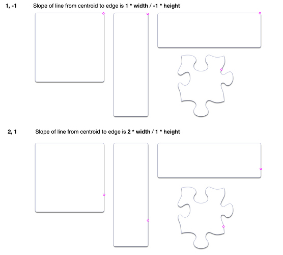
Given that magnet coordinates are relative, and project from a centroid to an edge, magnet positions that are invariant under shape resizing might need to be achieved by constructing a composite (grouped) object.

Perhaps you could attach magnets to an ‘invisible’ shape (no fill, edge or shadow), and group it with the displayed object, ungrouping for a moment if you need to resize the visible partner ?

A script might, for example,

  • make a duplicate of the selected object
  • strip magnets from the duplicate
  • remove line shadow and fill from the still ‘magnetized’ orginal
  • place the visible copy on top of (or below ?) the hidden magnet-bearer
  • group the pair

15


Properties (from clipboard):

{
    "Layers": [
      {
        "Print": true,
        "Lock": false,
        "View": true,
        "Name": "Layer 1",
        "Artboards": false
      }
    ],
    "Origin": "{0, 0}",
    "Scale": "No scale",
    "Color": {
      "g": "1",
      "space": "srgb",
      "r": "1",
      "b": "1"
    },
    "GraphicsList": [
      {
        "LayerIndex": 0,
        "Style": {
          "shadow": {
            "Draws": "NO"
          },
          "stroke": {
            "Draws": "NO"
          },
          "fill": {
            "Draws": "NO"
          }
        },
        "Graphics": [
          {
            "Bounds": "{{85.039370850315237, 137.48031620800964}, {103.46456786788349, 167.24409600561989}}",
            "Flow": "Clip",
            "Style": {
              "shadow": {
                "Draws": "NO"
              },
              "stroke": {
                "Color": {
                  "g": "0.596063",
                  "archive": {},
                  "r": "0.56982",
                  "b": "0.745393"
                },
                "CornerRadius": 5,
                "Draws": "NO",
                "Width": 0.5
              }
            },
            "Text": {
              "VerticalPad": 0
            },
            "FitText": "Clip",
            "FontInfo": {
              "Size": 12,
              "Font": "Helvetica"
            },
            "Class": "ShapedGraphic",
            "ID": 15,
            "Magnets": [
              "{-1, -0.5}",
              "{-1, 0}",
              "{-1, 0.5}"
            ]
          },
          {
            "Bounds": "{{85.039370850315237, 39.685039730147096}, {103.46456786788349, 265.03937248348245}}",
            "Flow": "Clip",
            "Style": {
              "stroke": {
                "Color": {
                  "g": "0.596063",
                  "archive": {},
                  "r": "0.56982",
                  "b": "0.745393"
                },
                "CornerRadius": 5,
                "Width": 0.5
              }
            },
            "Text": {
              "VerticalPad": 0
            },
            "FitText": "Clip",
            "FontInfo": {
              "Size": 12,
              "Font": "Helvetica"
            },
            "Class": "ShapedGraphic",
            "ID": 16
          }
        ],
        "Class": "Group",
        "ID": 17
      }
    ]
  }

You could, for example, put a pair of such shapes into the OmniGraffle clipboard (for pasting into a canvas), by running the JavaScript for Automation script below, from Script Editor etc.

(Using JXA rather than the faster omniJS here, simply because it has full access to the clipboard, and some useful ObjC functions)

(() => {
    'use strict';

    ObjC.import('AppKit');

    // GENERIC FUNCTIONS --------------------------------------

    // Left :: a -> Either a b
    const Left = x => ({
        type: 'Either',
        Left: x
    });

    // Right :: b -> Either a b
    const Right = x => ({
        type: 'Either',
        Right: x
    });

    // bindLR (>>=) :: Either a -> (a -> Either b) -> Either b
    const bindLR = (m, mf) =>
        m.Right !== undefined ? (
            mf(m.Right)
        ) : m;

    // plistLR :: JS Object -> Either String XML
    const plistLR = jso => {
        let error = $();
        const xml = $.NSString.alloc.initWithDataEncoding(
            $.NSPropertyListSerialization
            .dataWithPropertyListFormatOptionsError(
                $(jso),
                $.NSPropertyListXMLFormat_v1_0, 0,
                error
            ),
            $.NSUTF8StringEncoding
        );
        return Boolean(error.code) ? Left(
            error.localizedDescription
        ) : Right(
            ObjC.unwrap(xml)
        );
    };


    // MAIN -----------------------------------------------------------------
    const contentType = 'com.omnigroup.OmniGraffle.GraphicType';

    const dctLinkBack = {
        "Layers": [{
            "Print": true,
            "Lock": false,
            "View": true,
            "Name": "Layer 1",
            "Artboards": false
        }],
        "Origin": "{0, 0}",
        "Scale": "No scale",
        "Color": {
            "g": "1",
            "space": "srgb",
            "r": "1",
            "b": "1"
        },
        "GraphicsList": [{
                "Points": [
                    "{158.74015892058841, 357.87401899507699}",
                    "{246.6141754659142, 357.87401899507665}"
                ],
                "LayerIndex": 0,
                "AllowLabelDrop": false,
                "Head": {
                    "Info": 3,
                    "ID": 60
                },
                "Style": {
                    "shadow": {
                        "Draws": "NO"
                    },
                    "stroke": {
                        "Legacy": false,
                        "HeadArrow": "FilledArrow",
                        "Color": {
                            "g": "0.149131",
                            "space": "srgb",
                            "r": "1",
                            "b": "0"
                        },
                        "TailArrow": "0",
                        "Width": 2
                    },
                    "fill": {
                        "Draws": "NO"
                    }
                },
                "FontInfo": {
                    "Size": 12,
                    "Font": "Helvetica"
                },
                "Class": "LineGraphic",
                "ID": 65,
                "Tail": {
                    "Info": 3,
                    "ID": 63
                }
            },
            {
                "LayerIndex": 0,
                "Style": {
                    "shadow": {
                        "Draws": "NO"
                    },
                    "stroke": {
                        "Draws": "NO"
                    },
                    "fill": {
                        "Draws": "NO"
                    }
                },
                "Graphics": [{
                        "Bounds": "{{246.61417546591417, 232.44094699086173}, {103.46456786788349, 167.24409600561989}}",
                        "Flow": "Clip",
                        "Style": {
                            "shadow": {
                                "Draws": "NO"
                            },
                            "stroke": {
                                "Color": {
                                    "g": "0.665044",
                                    "archive": {},
                                    "r": "0.636504",
                                    "b": "0.791745"
                                },
                                "CornerRadius": 5,
                                "Draws": "NO",
                                "Width": 0.5
                            }
                        },
                        "Text": {
                            "VerticalPad": 0
                        },
                        "FitText": "Clip",
                        "FontInfo": {
                            "Size": 12,
                            "Font": "Helvetica"
                        },
                        "Class": "ShapedGraphic",
                        "ID": 60,
                        "Magnets": [
                            "{-1, -0.5}",
                            "{-1, 0}",
                            "{-1, 0.5}"
                        ]
                    },
                    {
                        "Bounds": "{{246.61417546591417, 134.64567051299912}, {103.46456786788349, 265.03937248348245}}",
                        "Flow": "Clip",
                        "Style": {
                            "stroke": {
                                "Color": {
                                    "g": "0.665044",
                                    "archive": {},
                                    "r": "0.636504",
                                    "b": "0.791745"
                                },
                                "CornerRadius": 5,
                                "Width": 0.5
                            }
                        },
                        "Text": {
                            "VerticalPad": 0
                        },
                        "FitText": "Clip",
                        "FontInfo": {
                            "Size": 12,
                            "Font": "Helvetica"
                        },
                        "Class": "ShapedGraphic",
                        "ID": 61
                    }
                ],
                "Class": "Group",
                "ID": 59
            },
            {
                "HFlip": "YES",
                "LayerIndex": 0,
                "Style": {
                    "shadow": {
                        "Draws": "NO"
                    },
                    "stroke": {
                        "Draws": "NO"
                    },
                    "fill": {
                        "Draws": "NO"
                    }
                },
                "Graphics": [{
                        "Bounds": "{{55.275591052704897, 232.44094699086207}, {103.46456786788349, 167.24409600561989}}",
                        "HFlip": "YES",
                        "Flow": "Clip",
                        "Style": {
                            "shadow": {
                                "Draws": "NO"
                            },
                            "stroke": {
                                "Color": {
                                    "g": "0.665044",
                                    "archive": {},
                                    "r": "0.636504",
                                    "b": "0.791745"
                                },
                                "CornerRadius": 5,
                                "Draws": "NO",
                                "Width": 0.5
                            }
                        },
                        "Text": {
                            "VerticalPad": 0
                        },
                        "FitText": "Clip",
                        "FontInfo": {
                            "Size": 12,
                            "Font": "Helvetica"
                        },
                        "Class": "ShapedGraphic",
                        "ID": 63,
                        "Magnets": [
                            "{-1, -0.5}",
                            "{-1, 0}",
                            "{-1, 0.5}"
                        ]
                    },
                    {
                        "Bounds": "{{55.275591052704897, 134.64567051299912}, {103.46456786788349, 265.03937248348245}}",
                        "HFlip": "YES",
                        "Flow": "Clip",
                        "Style": {
                            "stroke": {
                                "Color": {
                                    "g": "0.665044",
                                    "archive": {},
                                    "r": "0.636504",
                                    "b": "0.791745"
                                },
                                "CornerRadius": 5,
                                "Width": 0.5
                            }
                        },
                        "Text": {
                            "VerticalPad": 0
                        },
                        "FitText": "Clip",
                        "FontInfo": {
                            "Size": 12,
                            "Font": "Helvetica"
                        },
                        "Class": "ShapedGraphic",
                        "ID": 64
                    }
                ],
                "Class": "Group",
                "ID": 62
            }
        ],
        "ZoomLevel": 1
    };

    // og7pBoardFromLinkBackPlist :: String -> IO Bool
    const og7pBoardFromLinkBackPlist = plistXML => {
        const pb = $.NSPasteboard.generalPasteboard;
        return (
            pb.clearContents,
            pb.setStringForType(
                $(plistXML),
                'com.omnigroup.OmniGraffle.GraphicType'
            )
        );
    };

    // Assumes OG Linkback JSO format
    // og7pBoardFromJSO :: Object -> IO Clipboard
    const og7pBoardFromJSO = jso =>
        bindLR(
            plistLR(dctLinkBack),
            xml => Right(og7pBoardFromLinkBackPlist(xml))
        );

    return og7pBoardFromJSO(dctLinkBack);
})();

And if you want to view and edit a JSON representation of graphics which you have created, for re-pasting (with a script like that above) into OG, you can:

  1. Copy the graphics into the clipboard manually, and then
  2. Run the following script to convert the clipboard graphics to a JSON representation of them.

(In short, a slightly more declarative approach to scripting the creation of custom shapes and groups)

(() => {
    'use strict';

    ObjC.import('AppKit');

    // Left :: a -> Either a b
    const Left = x => ({
        type: 'Either',
        Left: x
    });

    // Right :: b -> Either a b
    const Right = x => ({
        type: 'Either',
        Right: x
    });

    // bindLR (>>=) :: Either a -> (a -> Either b) -> Either b
    const bindLR = (m, mf) =>
        m.Right !== undefined ? (
            mf(m.Right)
        ) : m;

    // elem :: Eq a => a -> [a] -> Bool
    const elem = (x, xs) => xs.includes(x);

    // isLeft :: Either a b -> Bool
    const isLeft = lr =>
        lr.type === 'Either' && lr.Left !== undefined;

    // String copied to general pasteboard
    // copyText :: String -> IO Bool
    const copyText = s => {
        const pb = $.NSPasteboard.generalPasteboard;
        return (
            pb.clearContents,
            pb.setStringForType(
                $(s),
                $.NSPasteboardTypeString
            )
        );
    };

    // MAIN ------------------------------------------------------------------

    const
        ogType = 'com.omnigroup.OmniGraffle.GraphicType',
        pBoard = $.NSPasteboard.generalPasteboard;

    return bindLR(
        elem(ogType,
            ObjC.deepUnwrap(pBoard.pasteboardItems.js[0].types)
        ) ? Right(
            JSON.stringify(
                ObjC.deepUnwrap(
                    pBoard.propertyListForType(ogType)
                ),
                null, 2
            )
        ) : Left('OG7 graphics not found on clipboard'),
        strJSON => (
            copyText(strJSON),
            Right('Clipboard now contains JSON-encoded OG7 graphics')
        )
    );
})();

Thanks so much for posting this - creating an item in our dev database to track the issues you’re raising here/get it in front of the appropriate engineering folks. Appreciate it very much!

Thank you. That means a lot and I appreciate you letting me know! Please ask them to post if there’s anything in a nightly build or an official update that they’d like tested out.

Checking in on this topic. Has there been any movement on improving the internal consistency of magnet coordinate systems?

Happy to help! Items are on file and tentatively scheduled for inclusion in a future update but haven’t been worked on yet.

Happy holidays - wondering how hard I should be wishing to find something under the tree? ;)

Thank you!

Revisiting this topic to see whether there have been any recent developments.

improving the internal consistency of magnet coordinate systems

As far as I’m aware, they have always (and consistently) been radial projections from a centroid to the edges of the shape, intersecting at points determined by the geometry of that shape…

Not sure that there has ever been any variation or inconsistency in that … (or that a change seems particularly probable)

I think we may, alas, have failed to notice, when you were up at 4am in Feb 2018, that a slight misunderstanding had arisen:

The multiple internal scales and coordinate systems for magnets are driving me up a wall

Not surprising that you were feeling driven up the wall – it was just a misunderstanding … :-(

  • There is no “internal scale” at all (the pair of values for each magnet expresses a ratio)
  • The only “coordinate system” is radial (the ratio gives the slope of a line which has its origin at the centroid of the shape. The magnet position is the point at which that line intersects with the edge of the shape).

We should have spotted this misunderstanding a year and a half ago … I can’t speak for why it was “entered in the issue tracker” before it had been understood …

This is how it actually works, and how it is possible to specify a magnet position (more specifically, the slope of a line (from the centroid of the shape) to the magnet)