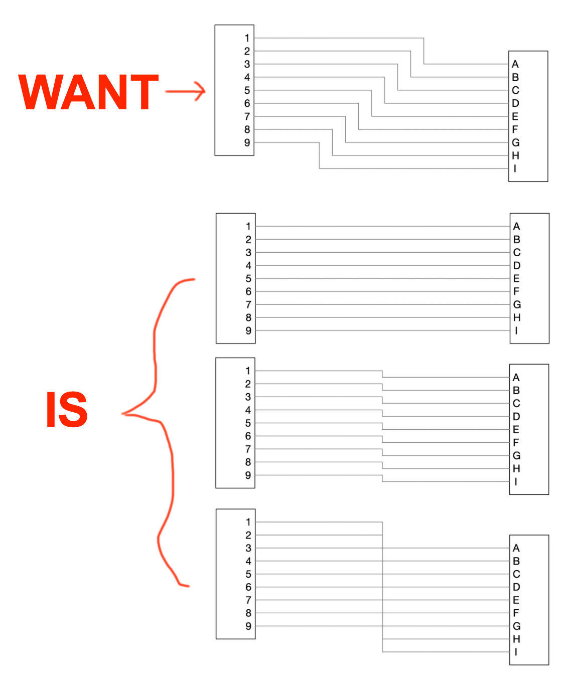
Trying to make an electrical diagram with wiring depicted as many orthogonal lines connecting many pins on many different connectors. The desired look is to have lines running parallel to one another and maintain consistent spacing relative to each other as they turn. Example of the desired look is shown in the first image below.
The first image was created by manually manipulating the lines for spacing. This would be a lot of work on a diagram with hundreds of wires, especially because the effort would need to be updated any time a “connector” was repositioned on the diagram. I am used to this functionality as default in Visio, but cannot figure out how to accomplish this automatically in OG. The behavior I am seeing in OG is that as the “connectors” are moved around, lines begin to simply stack on top of one another as shown in the bottom three images.
Does anyone know how to achieve the desired look automatically?
Welcome to the OG forums.
OmniGraffle
I am an OG V5 guru (and not about to move), so my answer excludes the later releases. Having said that, given your post, I don’t think the later releases of OG have changed in this regard.
The short answer is no.
I have hundreds of diagrams that have that sort of need, a few explicitly electrical or wiring or cable, and many more eg. pure logic diagrams, where the lines must match and move as you have described.
- Placing one Midpoint on each line is no problem at all. The Midpoint is the exact location where I want the line to “turn” 90º.
- I do not recommend using the automatic middle of the Line (a blue bar) instead of a Midpoint (a blue diamond).
- In general, the point at which the line makes an automatic “turn” is not the point that I want it to turn. So I have to create and place a Midpoint anyway.
- Note, the Midpoint is now fixed on the Canvas, it is not relative to the Object at the Start or End of the Line. That is OG behaviour, and once you get used to it, it is not a problem.
- You can Select the collection of Lines [between the two Objects] plus one Object [not both] and move them together. Or move each Line individually.
- The automatic behaviour you desire breaks down when the lines have labels. Virtually all my Lines have text or shape Objects as labels.
Grid
Make sure that you use a Grid, and SnapToGrid, which is an absolute requirement to make any diagram look good. I base mine on the paper size, and then:
- Major Grid Spacing 2cm
- Minor Grid Spacing 10
- Change to 20 when finer graduation is required, for the duration,then switch back
Visio
I am not a Visio expert, but I do have ongoing experience, in that I often have to export my OG diagrams onto a customer’s Windoze system, and then tweak it to fix the issues that do not get translated perfectly. I have not seen that sort of automatic spacing in Visio, Further, while that looks and works fine on a simple example, it does not work at all where the diagram is large, or where it has many wire-to-connector components. Point being, Midpoints on the lines are demanded.
OmniGraffle Enhancement Request
Worth having.
That a series of parallel lines that are:
- equidistant [to each other],
- and have no Midpoints,
- When an Endpoint Object is moved, that the lines must remain equidistant.
- With the automatic break-point being the overall middle, ie. the middle of all the affected lines, in toto.
- Ignore text or shape objects that are labels on the lines (let the draftsman move them).
2 Likes
Thanks for the reply, helpful - although I do wish the behavior you describe in that enhancement request already existed.
1 Like