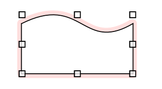
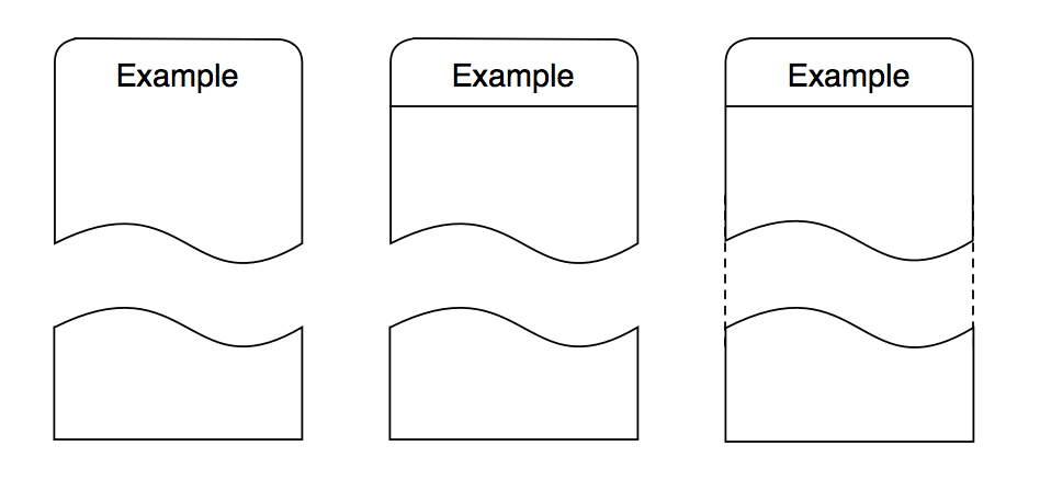
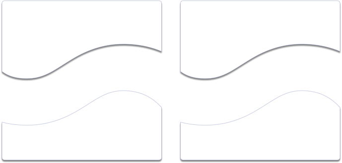
Can someone suggest the easiest way to make a diagram like this?
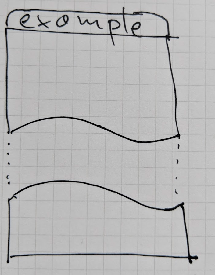
The difficult parts: 1. how to make the curved parts 2. How to make only 2 corners rounded instead of all 4
Can someone suggest the easiest way to make a diagram like this?
The difficult parts: 1. how to make the curved parts 2. How to make only 2 corners rounded instead of all 4
Perhaps:
?
How do I do curved line? The Connection tool lets me do a line, but I can’t add control handles to any of the control points. And the Shape tool won’t let me create a shape with 2 vertices
ah, it’s the “Line Type” which needs to be bezier…trying to figure out how to do “Thicked” part now
Thanks, figured it out, the Object Subtract/Add seems to be useful here, can also use it for doing “rounded corners on top only”
I would approach the task as follows:
Appreciate that you want one rectangle, which is to be split, by a curved line (or anything else, for other similar requirements). That way, you will get edges, etc, perfectly lined up (otherwise you have two objects, slightly different, and you will have to fiddle).
Always use a grid, and stick to it.
You need simple instructions for handling Bezier Lines and EditPoints, so this might be a bit long, but in practice it is quite simple.
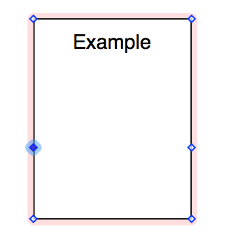
Draw a rectangle, with no corner radius (0 pts).
Duplicate it, so as to retain the original rectangle. Edit/Shapes/MakePointsEditable.
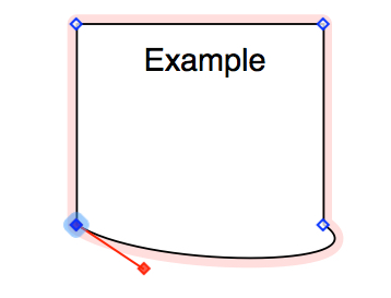
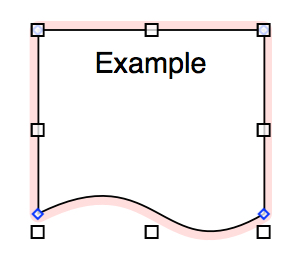
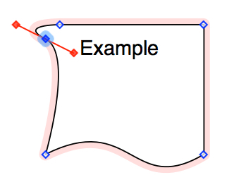
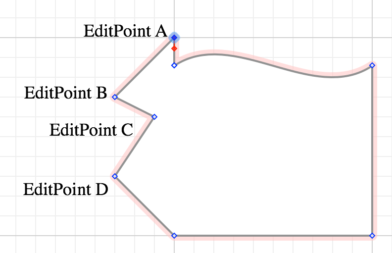
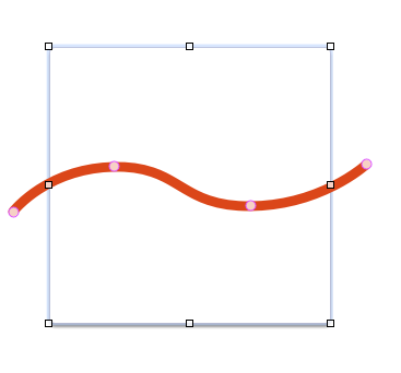
Add two EditPoints (blue diamond) at the locations where the [imaginary] line will intersect with the rectangle.
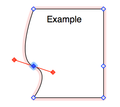
Create Bezier handles on those two EditPoints (after selecting the EditPoint, Command-drag … that will cause two handles (red filled diamonds) to appear).
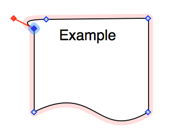
There is one BezierHandle for each direction away from the EditPoint. We need to manipulate each BezierHandle separately. Select and Option-drag one BezierHandle. Take the BezierHandle relating to the NW corner (on the left in this example), and drag it into the origin (the EditPoint). That will cause the left edge to be straight.
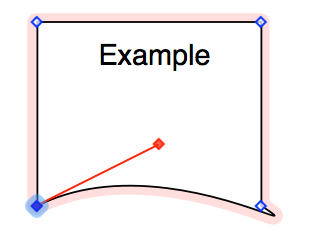
Now perform the same action on the second EditPoint.
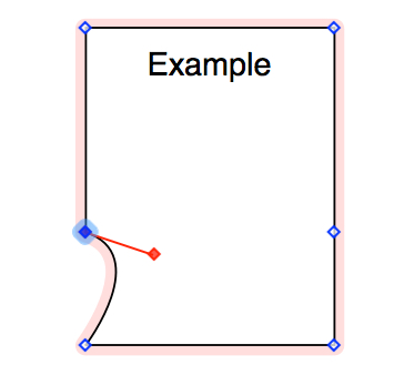
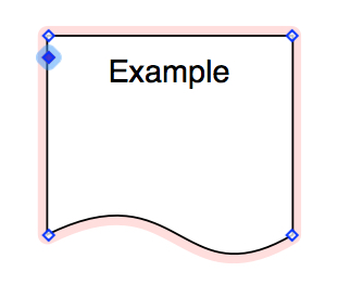
Delete the two bottom EditPoints (SW & SE corners). The two created EditPoints will now be the SW & SE corners.
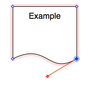
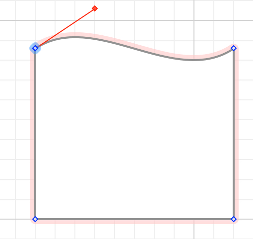
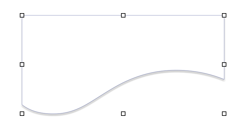
Each created EditPoint has one BezierHandle (because we deleted the second). Each BezierHandle relates to next EditPoint. Select and drag each EditPoint, so as to obtain the desired curve. In this example, drag the SW EditPoint up and to its righ.
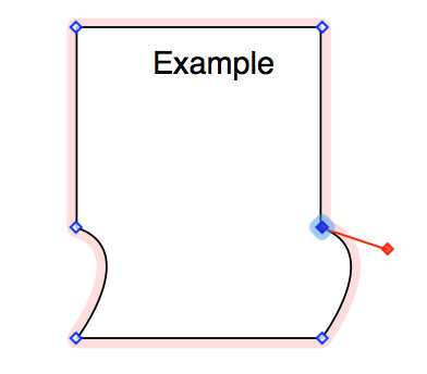
Drag the SW EditPoint up and to its right, the SE EditPoint down and to its left. Keep the BezierHandles equi-distant, such that the curve is even and balanced.
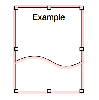
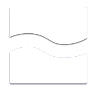
Duplicate the original rectangle [A.1], and place it behind the TopObject.
Select both objects, and Edit/Shapes/SubtractShapes.
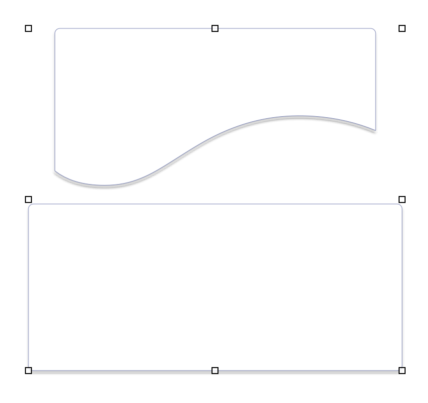
The BottomObject is complete. The two objects have the exact same curve (one as its bottom edge, and the other as its top edge), and they line up on the grid the exact same way.
Since there are two separate objects, it is no problem to implement round corners on one and not the other. However, we cannot use the Style/Stroke/CornerRadius facility because that will round all the corners, and we want just two corners rounded.
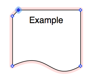
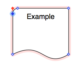
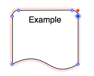
Changing an EditPoint (currently a square corner) into a round corner is easy enough, but again, laborious to explain, and much of it has been explained above. Let me give you a sequence of diagrams instead.
The idea is, add an EditPoint at each corner, one grid-increment offset, and use the BezierHandle (again only one is required) to form a curve, which makes the corner round.
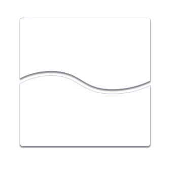
Line up the TopObject and the BottomObject on the same vertical axis, creating the desired gap between them. This will be easy, because they were created out of the same original rectangle, and drawn on the same grid.
Add a horizontal line to separate the heading.
Add two vertical lines to show the continuity. Place them behind the objects.
Select all five objects and Group them. You can modify either the Group as a single object, or any of its components (eg. to create a larger gap, or change the properties of the dotted lines).
Enjoy.
Thanks for the in-depth response.
Unfortunately, this doesn’t seem to work in Omnigraffle 7.5
It gives me the following shape after subtraction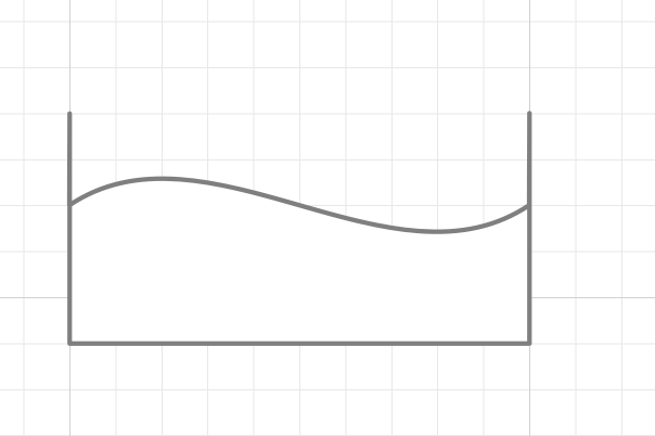
curvy-intersect-bug.graffle (2.6 KB)
You are welcome.
The first thing to understand is, in general, overall, OG6 is worse than OG5, and OG7 is out in never-never-land. This problem does not happen in OG5. To perform any given set of tasks, the more “advanced” the product, the more human actions are required.
Nevertheless, it can be fixed (ie. with further work, in OG7).
Second, when one sees that sort of a result, one needs to recognise it as an error due to OG lining up of EditPoints on the grid incorrectly. What you are seeing is an object with extra EditPoints that are left behind because some of the EditPoints before the subtraction were no perfectly lined up. Stated another way, OG determined the coordinates of the EditPoints incorrectly. And then, that OG7 has more occurrences of such than OG5.
Therefore the first attempt at recovery is to get the EditPoints of the two source objects lined up on the grid, before the Edit/Shapes/SubtractShapes. That should improve the result (less occurrences of mis-aligned EditPoints)
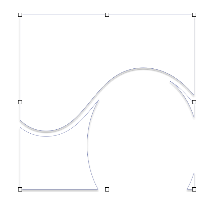
If that does not work, do this on the object resulting from the subtraction. We know they are extraneous EditPoints:
Which were on top of each other … moved away from their original positions, so that they are visible.
Cheers
Thanks, looks like I can fix it by deleting the extra points on the resulting shape (after subtraction). Pretty sure there were no extra edit points on the shape before subtraction, tried it both with rectangle and custom shape, with same result
Yes, the extraneous EditPoints are created by the Subtraction function of the later releases (OG 6 & 7), it does not happen in OG5. As you can see, when the background object was covered by the foreground object, it “thought” there was a sliver of the background object visible. I love the sequence of four extraneous EditPoints, it was crazy.
In a more intense set of objects, I have played with line widths, and line types and precise placement, in order to eliminate this bug. No gain. Manual removal of the extraneous EditPoints is always required.
Cheers
draft8, that’s a brilliant, and simple way to get it done. Thanks!
But is there an easy way to separate the top and bottom halves into two separate objects, e.g. so I can easily adjust the gap between the two? I was able to accomplish this by duplicating the entire composite object and then deleting, point-by-point, the top half of one copy and the bottom half of the other copy, but that seems clumsy.
First thought might be to:
Then repeat with the other copy and its upper shape.
Two copies,
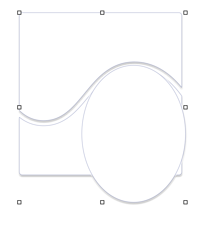
Rectangle laid over lower sub-shape of one copy, and front and back both selected:
Edit > Object > Subtract Shapes
( Then repeat to subtract upper shape from other copy )
Thanks! It still takes a lot of clicking, though. It would be nice if OG allowed us to “ungroup” it, and make it into two separate objects.