I find that magnets are often difficult to place in such a way that the line from box to box will be straight. I’d rather do this without changing the line from orthogonal to straight so as to get straight lines. I have noticed that the magnet tries to line up with the magnet on the other side of the box, so I delete that other magnet and this sometimes works and sometimes does not work. Overall, getting magnets to stay exactly where I want them is a major pain. Is there a setting somewhere that can allow this? So far, I have not found it.
Attached is a picture showing what I mean. In this case the magnet seems to be trying to line up with a magnet that is no longer there on the other side of the box.
Seven Days. This is a question the developers should answer. Hope they are getting paid.
This is going to require some explanation, so bear with me. Further, hopefully other seekers will find something useful in my answer, therefore I will try to be precise. Once you understand this, and gain a bit of experience, it is actually much easier than the length of this post suggests.
No kidding. Magnets are a major pain in the backside. There are a number of facilities in OG are non-intuitive or anti-intuitive, but this one takes the cake in the Tools category.
They have tried to improve it over the decades, over the versions, and worse, over different development teams, with no particular improvement at the usage end. The older versions bounce around a lot less.
Therefore we can conclude, and etch into our consciousness, the first principle:
Principle 1
Rather than trying to get the Tool (Magnets or whatever)
to work the way we want them to (which is impossible),
we must learn the way the Tool (Magnets (or whatever) work.
It is a principle because it is a starting basis, and it will save you time over the whole course of tasks, as well as from tearing your hair out throughout the exercise.
Yes. Absolutely. Lines, and here Orthogonal Lines, work just fine. Therefore the second principle:
Principle 2 Use something that works, to its full ability (do not use something that is broken)
Corollary
Do not use something other than for its purpose.
(It needs to be stated, OG “straight” Lines are not straight, they are diagonals. One needs to hold SHIFT down to draw straight Lines, and ensure that they have just the two angles.)
Two good features of an Orthogonal Line that must be noted (they will be important later):
it can be precisely set, and placed, simple by adding a MidPoint
A Line segment can be “switched” from the horizontal to the vertical and vice versa, simple by adding a MidPoint.
I rarely use diagonals.
No. Despite decades of asking.
In the more recent versions, there is something about “attach to centre” posted in the forum. But it does not work as intended (by the developers) or as expected (by the users). It is even more silly because the setting is at the object level.
In any case, none of that matters (either the latest greatest useless facility, or those that are dreamed up in future). What matters is the first principle, to learn how the Magnets operate, so that you can work in a determined manner, such that the use of the tool is predictable.
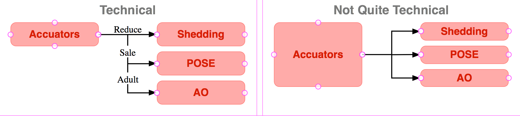
1 Technical Diagram
Before we dive into the specifics, there is one thing that would seriously assist you, and improve your diagrams generally. Applying the first principle, re diagram standards. You are drawing a non-standard diagram. If you maintain standards, the diagram will look much better; be easier to understand; and last but not least, it will have less problems in the erection. I am not going to labour this point (much can and should be said), but I will provide a pointer or two.
Technical diagrams are semantic, or symbolic. It pertains to Logic. Generally, that means the size of each object should not matter, which really means, they should all be the same size (think, all the symbols in a FlowChart).
It is the shape (Form) of the symbol that tells the reader what it is, not the size or colour.
[I have no idea what your Accuator is, but] if it is a technical object that relates to the objects at right, I seriously doubt that it has a separate port for each attached object.
It is common, but still incorrect, to resize the object to fit the allegedly artistic “looks nice” requirement.
The [Accuator] Event would be text on each arrow. If that is the reason you want long lines, no, there are better ways.
Then there is the business of plural. If you draw all the thingees as a group in a single object “Accuators”, I can guarantee, your drawing will be difficult, and it will keep changing.
If the diagram were thusly elevated, the drawing problem completely disappears.
Nevertheless, the question remains, and I will answer it.
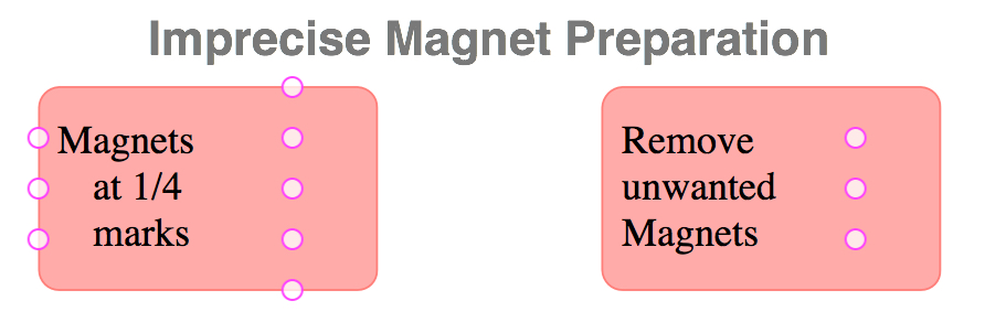
2 The Wrong Way • Imprecise
2.1 Magnet Preparation
Most of us know, even if only subconsciously, that we have to mess with the Magnets (rather than the Lines). If you read the forum, there is some info re AttachToCentre, and even before its advent, we knew to place the Magnet at or near the centre, in order to get what we want.
Now in the forum, this has been explained badly, and people cannot get what they want.
It lacks precision, people cannot walk away with confidence, they cannot use the tool in a predictable way.
Last, in order to know what is precisely right, it is very helpful to know what is wrong: the common looks-and-feels-right but is wrong because it lacks the precision it is precisely supposed to have.
The wrong thing first, for those who have followed other posts on the subject, and laboured to no avail, so that you understand exactly what is wrong.
You have evidently tried some portion of this, in that you have placed the magnets at the edges and then messed with them, and you have noted the various types of “snap” that the Magnets do.
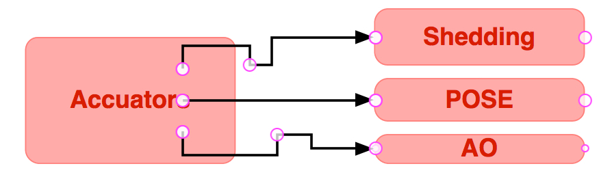
This is the common way: set some arbitrary Magnets on the object, here at the one-quarter points along the edges, that it “snaps” to.
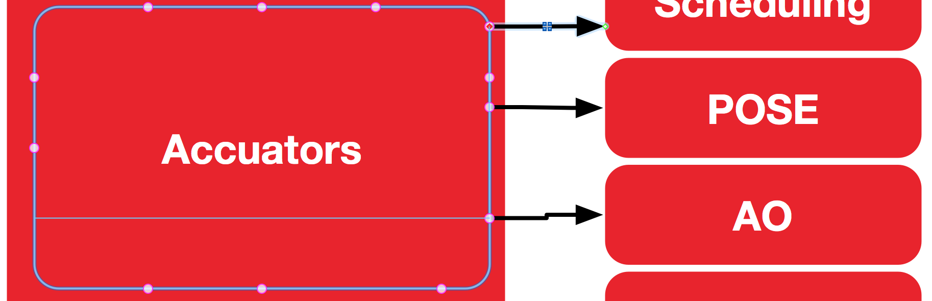
Next, create some Magnets in the centre, close to the right edge (because that is where we want the lines to go from).
Notice, on the Accuators object, the centre-top and centre-bottom lines go up and down respectively, instead of right, which we want. The developer was using a crystal ball instead of asking users. It has to do with the size of the object, and the proportion from the centre.
3 The Better Way • Precise
Four steps.
3.1 Magnet Preparation
The method is to get the Magnets close enough to the centre (on the horizontal), and close enough to the right edge.
Of course, the same goes for the left; top; and bottom edges.
The dotted line describes the area outside of which (for this object, proportionately)the Magnets must be placed, in order to obtain Magnets that will work.
Here, I chose 5 Magnets per side,
then added the three in the centre so that it is easy (snaps to the Magnets on the edges),
then removed all but the three desired Magnets.
Essentially we are telling the developer who coded the “attach to centre” “snap” facility to get stuffed, and we are doing it ourselves.
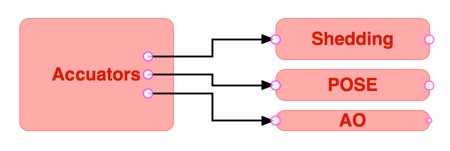
Notice, the three Magnets in 3.1 Magnet Preparation are just a little closer to the centre horizontal, and a little closer to the right edge, than in 2.1 Magnet Preparation.
The automatic MidHandles on the Orthogonal Lines are just fine: all lined up perfectly. That may be good enough for most people.
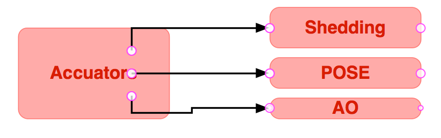
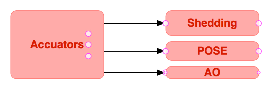
But not for us, we want more. We want Lines to look like they are straight from the source object, to the target object MidPoint.
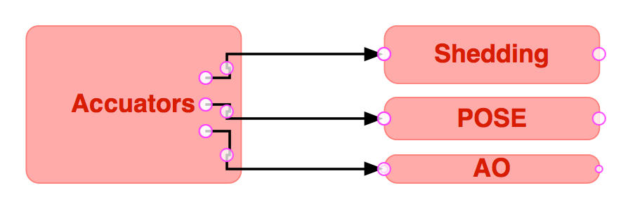
3.3 MidPoints
Double-click on the Line to create a MidPoint, and drag it inside the source object.
The location of each MidPoint in the source object must be between the correct Magnets and the edge (here, Magnets to the right, and the right edge).
The same goes for all four edges of the object.
If you are concerned about the tiny squiggles on the Line, do not worry. That has to do with the Grid I am using and SnapToGrid … in any case, they will be invisible soon.
Of course, I have not fixed the problem, I have only given a method of understanding the tool, and using it to get what you want. The Magnet Madness continues, at least for this decade.
If you move one or the other of those objects, the Lines will jump to a Magnet that it was not connected to.
Sometimes it will connect to an edge, rather than to a Magnet.
To preserve the connections, one must grab the source and target objects as a set. I Group them as a matter of course, in order to avoid moving one object and obtaining the undesired effect accidentally, but that is not feasible when I need the objects to be located on different layers.
Not a fault. If you move one of the target objects to a different location relative to the source object, ie. to a point below; above; or left of the source object, you will have to create a new Magnet to suit, and move the Line.