Hi all, I’m a new user to OG having moved from Visio on PC. I’m curious if I’ve just overlooked something, and there is an easy way to drag segments of an orthogonal line to make the line route the way you want it? I’m finding that even if I add midpoints, the line routing is completely nonsensical.
Simple example. I have an object centered vertically on the left. I have two objects equidistant from the center line on the right. I simply want a connector line going between the left object and each object on the right. I pick orthogonal, connect them, and OG has the lines exit the left object vertically, right angle, then horizontal over to my objects. In Visio, every segment of a connector line can be dragged, so I simply connect, drag the vertical segment over to the right side object, now my connector line exits to the right and goes vertical to the right-side objects.
I’ve found no way to do this in OG. By default, I can’t drag the line at all. If I add a midpoint, I can start to coax it to the right, but the vertical portion decides to segment itself half way up, without my having added any additional points, goes left, right, right back to the magnet on the object. I can try to add more and more midpoints to hide the weirdness behind the object I’m connecting to, but that seems over the top.
Any simple way to just drag orthogonal line segments to where you actually want them and have OG keep the segments straight?
Working with orthogonal lines in OG is actually very easy. I haven’t worked with Visio recently, but from the time that I did so, OG lines are much easier to work with than Visio lines. And far more precise.
The way that you perceive “segments” is probably an issue. Think MidPoints. However, note that after a line has a few MidPoints, yes, they start to act like segments.
The magnets on each shape are relevant. OG will try to make the connecting line, partly based on the magnets of the shapes that are being connected. So the first thing is to ensure that you have magnets located reasonably. Eg. on the right edge of the left box, and the left edge of the right box.
Please add a graphic as an example. (You may think that the words are descriptive, but they are not enough.) Or a link.
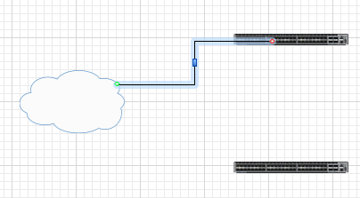
Ah, thanks for the help. I was able to add a magnet to the left object in an area closer to the right and that allowed the line to exit to the right. I’m still having one tricky issue with the right objects. This object is a representation of a network switch with 48 ports, and I plan to connect most of them, so there are numerous magnets on a very small object, and they seem to prefer exiting the magnet horizontally even though the shortest distance out of the object is vertical. Roughly the left third of the magnets head left, the middle third will indeed allow me to exit down, and the right third want to exit the magnet to the right. Here are some graphics:
The first one shows the left object with the desired exit direction after your help:
Will be adding more as followup posts since I’m only allowed to add one image to a post as new forum member.
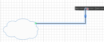
And that did indeed produce a line with a middle segment that could be dragged, exactly like I wanted:
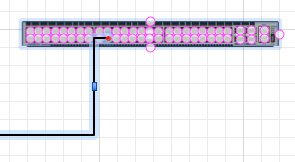
But as seen above, I can’t quite drag it all the way to the right to allow my line to have two total segments. Here’s a closeup of the right side object and its magnets:
Can I alter that object or its magnets in a way that let it exist vertically?
Thanks!
Have to say this forum is much easier to use from an attachment inclusion standpoint than common forums too; very pleased. Anxious to have enough posts to be able to do multiple images lol.
Actually, what you are experiencing is a basic drawing problem, not an OG problem. Understandable, given your newbie declaration. Then in addition to that, you are a newbie in OG.
1. Ugly as sin. Useful as mammaries on a bull. And that is your starting point.
You are trying to do too much with a single object, and thus making the object complex, and the use of it even more complex.
If you created that object with 48 magnets yourself, fair enough, I will show you how to correct it for the purpose.
If you got that object from a stencil off the internet, please be advised, that is stupid, immature, not at all thought out. I would never publish such a piece of junk. The internet is full of attractive stuff that is sub-standard. Anyone with a keyboard and two fingers (with or without connective tissue in-between) can publish.
People these days focus on the Skin (which is transient), and neglect the Form (which is purposeful, and stable).
[quote]Can I alter that object or its magnets in a way that let it exist vertically?
[/quote]
2. No problem at all. It is easier if I take you on a short tour, and your question will be answered in a more meaningful way.
3. So you want a switch. That can be scaled. With 48 Ports. That allows connection of lines to each port. That allows the connecting lines to behave in a reasonable way. Eg. lines to the lower set of ports go downward, lines to the upper set go upward. Et cetera.
Create a Form. In IT, if you know nothing about an object, the starting point of knowledge is its Inputs & Outputs. The Form of a Switch is its ports. What it looks like is irrelevant, and it changes all the time. What it does, as a Switch sitting in a rack, does not change.
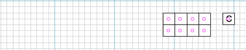
We want magnets, one on each port (not 48 on one object!), for the connecting lines. Let’s start with magnets in the centre. Here is a Switch with 8 ports, constructed from simple squares. You can Group them, to form a single shape.
Recall that the magnets on shapes at each end of the line are relevant. That OG will automatically try and use the magnets that do exist. Eg. magnets on the edges behave differently to magnets inside a shape. The centred magnets in the ports simulate your immature object, and its problems.
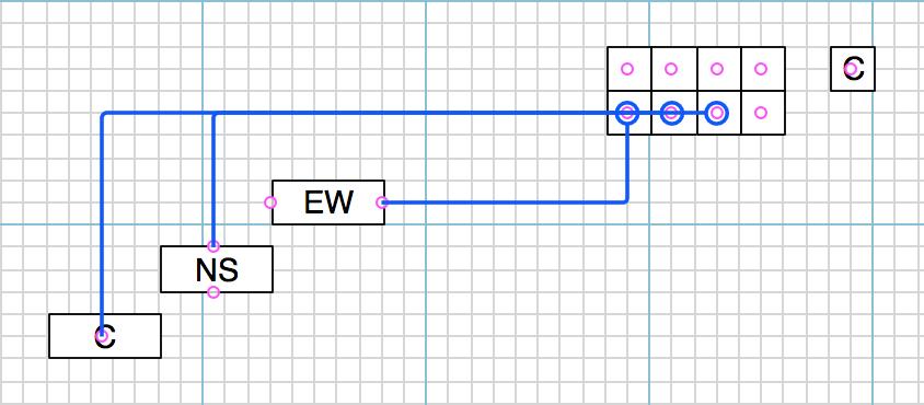
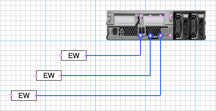
Here the target shapes have magnets at East-West; North-South; and Centre, so that you can examine the behaviour of each setting.
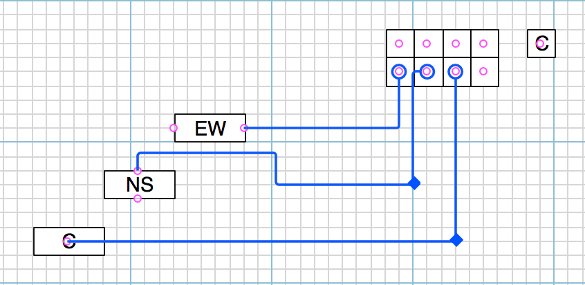
6. Nice try, but no cigar. East-West magnets look good on the target shapes. But Centre magnets on the Ports (not the Switch) are hopeless. Let’s fix that, and give the Ports North-South magnets.
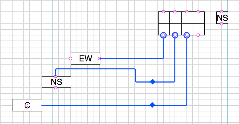
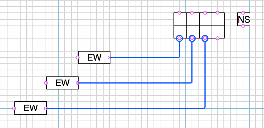
7. Getting better. Havana is looking likely. The MidPoints operate as expected, and are much easier to manage. Now let’s fix up the magnets on the target shapes. Obviously East-West is the one to go with.
Now that Switch, constructed of a Form (the structure that gives it purpose; meaning; usage) and a skin, rather than a skin-only, full of cancerous tumours, might be worth uploading to a stencil library. Because it is useful for the purpose. I would make it 48 ports; clean up the skin; etc. Beware of imitations.
Rum and cocaaaa cola,
Piña and eeeenchilada.
It has some nice features, a great skin. But it is full of bugs, just like OG. Just try getting six graphics that are created the same, to be displayed the same, and see if you have any hair left. Some imbecile thinks that if the filename has not changed, then the image has not changed as well. And the colours change, randomly. Too much skin and no idea of Form.